Ne555 timer pin diagram Set 2x e351d y 2x e355d timer ics gdr hfo envío mundial rápido el 555 timer ic pin diagram
Introduction to the 555 Timer - Circuit Basics
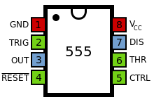
555 timer modes Pin diagram of 555 ic 555 timer ic
10+ 74153 ic pin diagram
12+ ic 7420 pin diagram555 ic lm555 timer ne555 diagram schematic internal block pinout fairchild modified pinouts ne556 working control pcb failure robot following 555 timer ic basic configuration complete diagram tutorial circuit package projects logic guide circuits electronic555 timer ic.
14 pin ic diagramIc 555 pinouts and working explained 12+ 4026 pin diagram555 timer diagram internal function pinout ic circuit schematic construction operation application working block functional electrical output voltage applications its.

555 timer ic: introduction, basics & working with different operating modes
4017 led chaser 555 ic circuit circuits using sine wave datasheet oscillator cd4017 running lights pcb pinout frequency constant lowList of 4000 series ic An overview of the 555 timer555 timer pinout circuit off delay turn chip before build.
555 timer pinout ne555 delay stopwatch sensor explanation circuitsPinout parallel pinouts circuits 555 timer ic pin diagramTimer 555 circuit diagram schematic ne555 datasheet pinout discrete kit does block circuits transistor works eleccircuit integrated functional pins connection.

555 timer circuits symbol circuit diagram configuration led inside drawing light
555 timer circuit electronics lambert555 integrado circuito Basic 555 timer circuitHow does ne555 timer circuit works.
Circuito integrado 555Cd4017 datasheet & pinout and working explained A complete basic tutorial for 555 timer icIntroduction to 555 ic with a simple application.

How to build a delay before turn off circuit with a 555 timer
Introduction to the 555 timerSimple time delay circuit using 555 timer Op amp inverting circuit non lm741 pinout diagram build pins chip connect555 ic timer diagram circuit astable pinout pins block description multivibrator ic555 internal ground structure explain functional circuits its connected.
Download free 555 timer pinout555 timer astable multivibrator circuit diagram 555 timer ic schematic diagramHow to build a non-inverting op amp circuit.

Ic 555 pinouts, astable, monostable, bistable modes explored
Timer pinoutIc 555 diagram block internal timer astable ic555 ne555 circuits integrated monostable pinouts bistable modes explored 10+ 74153 ic pin diagram.
.


How to Build a Delay Before Turn Off Circuit with a 555 Timer

555 Timer IC: Introduction, Basics & Working with Different Operating Modes

Introduction to the 555 Timer - Circuit Basics

12+ Ic 7420 Pin Diagram | Robhosking Diagram
Circuito Integrado 555 - Automatizacion

Simple Time Delay Circuit using 555 Timer

Download free 555 timer pinout - rafguitar